
QUICK INSTALLATION GUIDE

SAFETY
WARNING
Confirm compatibility before starting the installation
Disconnect the power source from the garage door opener before removing the existing photo-eye sensor or installing Infinity Shield®
Please use caution when handling the snap-in brackets to avoid cuts from sharp edges and pinching fingers between the door track and the brackets during installation
Do not operate the garage door until the Infinity Shield® installation is complete
After completing installation, confirm that the door stops when an object is placed in its path. If the door does not stop, immediately disconnect the power from the garage door opener and call customer support.
Please handle the transmit IR LEDs with care and avoid forceful impact and contact with sharp or abrasive objects
Door COMPATiBILITY
Minimum garage door width: 8 ft
Maximum garage door width: 18 ft
Minimum garage door height: 7 ft
Receiver
Transmitter
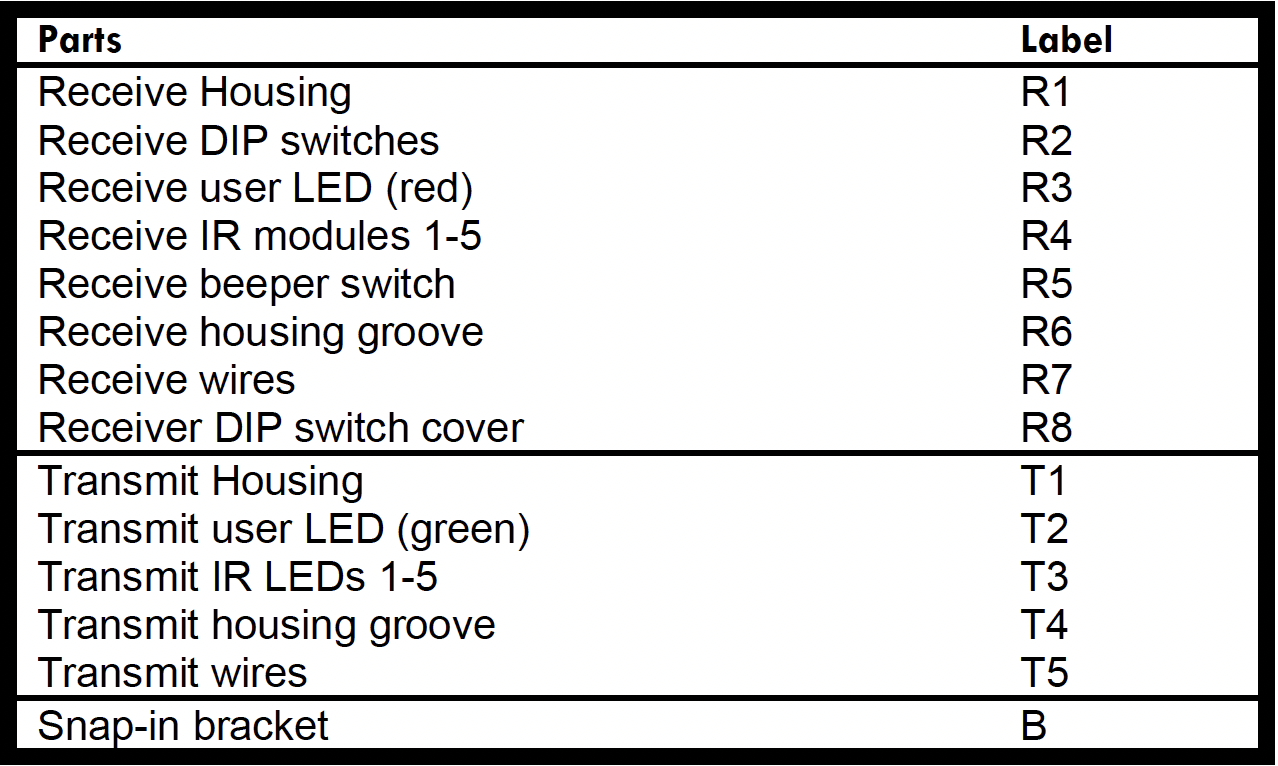
Referecence Labels

Installation INSTRUCTIONS
Estimated Time: 30–45 minutes
Confirm compatibility with the garage door opener.
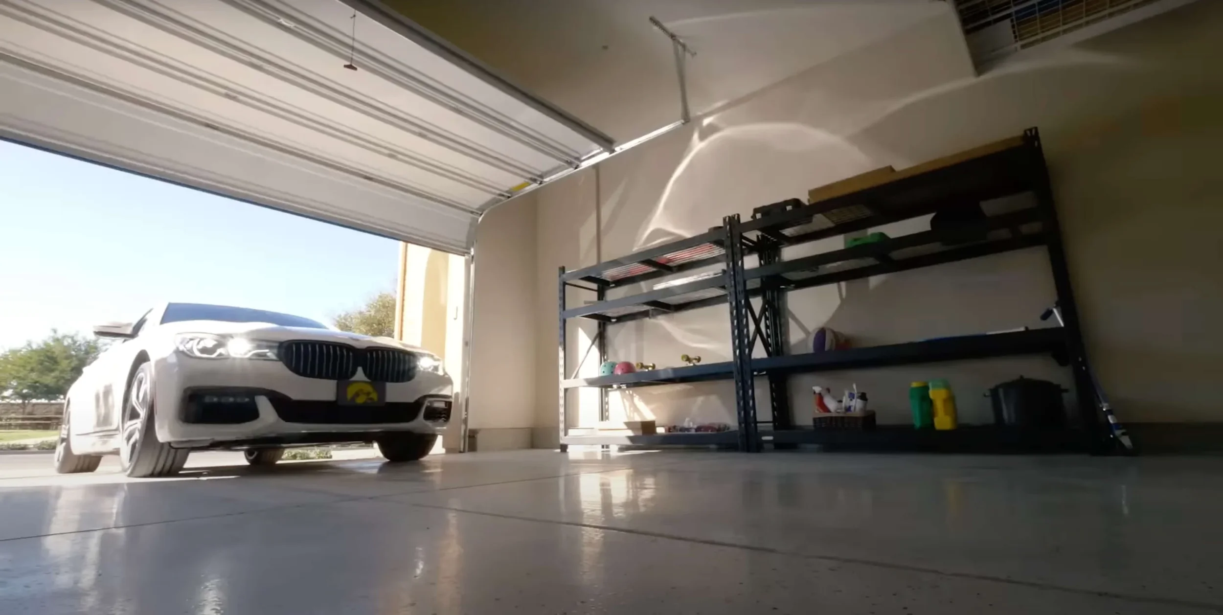
Check for objects on the moving door panels such as wide struts, support beams, door handles, locks, etc. that can potentially block the Infinity Shield beams. The top beam is 71.5” above the garage floor.
Unpack the parts from the box and lay on the garage floor covered by cardboard or on a table.
Disconnect the power from the garage door opener.
Only for new garage-door opener installation: Complete the installation process per the manufacturer’s instructions using the single-beam sensor included with the garage-door opener. Once completed, proceed to step 6.
Disconnect or cut the two wires from each of the existing sensors and remove them from both sides of the garage door.
For installation with multiple doors: follow the instructions in the user manual.
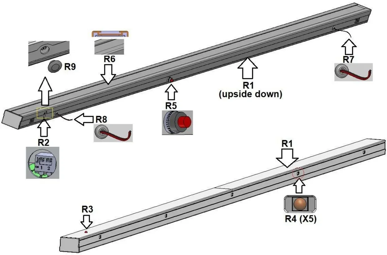
Remove the DIP switch cover (R8).
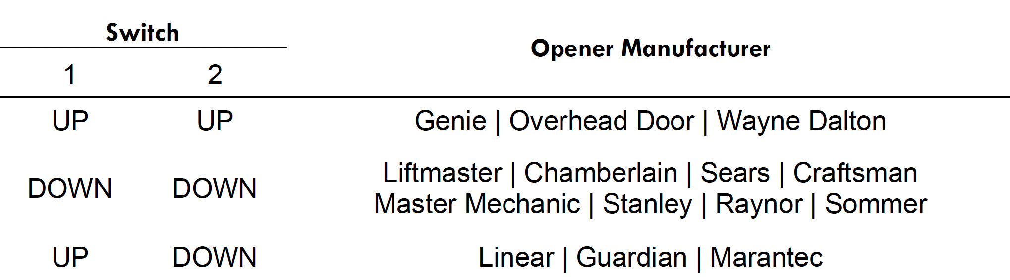
On the DIP switch (R2) of the receive housing (R1), set the switches to your model of the garage door opener. Use the tweezers that are included in the box. Using any other tool may damage the switches. Re-install the DIP switch cover (R8).
NOTE: If the DIP switch (R2) positions are changed, power to the unit must be turned off for at least 10 s and then turned on again, for the new configuration to take effect.For receive housing (R1):
a) Hold the housing next to the garage door track that it is intended to be installed on. Check to see if the snap-in brackets (B) interfere with any brackets on the tracks. Mark the desired bracket position on the receive housing (R1) with a piece of tape.b) Orient the claws of the snap-in brackets (B) to point in the direction of the IR modules (R4).
c) Snap in the brackets (B) into the receive housing groove (R6) by first inserting the center tab in the receive housing groove (R6) and then flexing the two outer tabs one at a time and inserting the tabs in the groove.
d) Clamp on the brackets (B) to the garage door track.
e) Connect the two wires (R7) to the two wires from the garage door opener with the included wire nuts or strip-less connectors. The red wire is positive and the black wire is negative. If the polarity of the wires from the garage door opener is unknown, it is possible to try one way first and the other way next if the first way is incorrect. If the polarity is correct, the user LED (R3) will light up red once power is restored to the garage door opener. Nothing will happen or get damaged if the polarity is incorrect.
For TX housing:
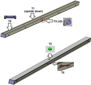
a) Hold the housing next to the garage door track (opposite side of the receiver housing) that it is intended to be installed on. Check to see if the snap-in brackets (B) interfere with any brackets on the tracks. Mark the desired bracket position on the transmit housing (T1) with a piece of tape.b) Orient the claws of the snap-in brackets (B) to point in the direction of the IR LEDs (T3).
c) Snap in the brackets (B) into the transmit housing groove (T4) by first inserting the center tab in the transmit housing groove (T4) and then flexing the two outer tabs one at a time and inserting the tabs in the groove.
d) Clamp on the brackets (B) to the garage door track.
e) Connect the two wires (T5) to the two wires from the garage door opener with the included wire nuts or strip-less connectors. The red wire is positive and the black wire is negative. If the polarity of the wires from the garage door opener is unknown, it is possible to try one way first and the other way next if the first way is incorrect. If the polarity is correct, the user LED (T2) will light up green once power is restored to the garage door opener. Nothing will happen or get damaged if the polarity is incorrect.
Connect power back into the garage door opener. If the system is installed correctly and none of the beams are blocked, the red receive user LED (R3) and green transmit user LED (T2) will light up.
The beeper can be turned on and off by pressing the receive beeper toggle switch (R5).
After completing installation
a) Confirm that the door does stop when an object is placed in its path. If the door does not stop, immediately disconnect the power from the garage door opener and call customer support.b) Turn on the beeper, park the car with the rear hatch open with the highest point intersecting the garage-door opening, and confirm that the beeper detects the hatch.